
• Fire Alarm Systems Tool-Kit

    Electrical Engineering
    – Duration:
    6
    mo.
    Fire Alarm Systems Tool-Kit

    This project began with the development of a toolset for calculating voltage drop in electrical circuits and gradually evolved into a full AutoCAD add-on through an adaptive, feedback-driven process. It serves as a prime example of a ‘work in progress’ approach, developed in close collaboration with the client over several months. Continuous exchanges of ideas and solutions ensured the software was perfectly tailored to the client’s workflows and requirements. Bellow is an illustration on how the app and the various tools evolved over time.
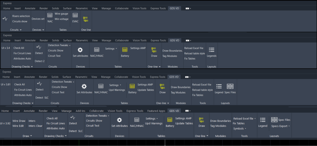
    Project evolution over time
    Project evolution over time

    Additionally, this process facilitated the seamless integration of various non-standardized data sources into the design workflow, including Excel spreadsheets, multiple CAD libraries and Access database information.

    Platform: AutoCAD

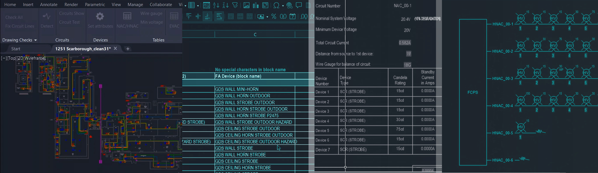
    • This module creates circuit data (number of devices, power source, wire lengths to each device) from chains of polylines and blocks. It has a system that links circuits across multiple levels and the detection algorithm was build to manage different drawing standards that changed over time (some drawings had circuit lines were entirely separate, others were merged into common sections to avoid overlapping)

    • A one-click solution for generating voltage drop tables in compliance with state regulations. The module includes two submodules, each designed for different circuit types and table requirements. Both submodules offer customizable settings and editing options, working with table templates that contain predefined formulas. This flexible approach allows templates to be modified at any time to accommodate changing requirements.

    • A one-click solution for generating electrical diagrams in compliance with state regulations.

    • An integrated solution for loading external data, verifying and assigning values to devices (dynamic blocks) by combining and filtering drawing data, user input, and specification table data. This ensures that each device receives the correct attributes in accordance with design requirements—such as candela values based on the covered area—and manufacturer specifications.